TRUCK EDIDTION!!!!!!! (yay) |
Here's a new version of the tachometer page dedicated to 70's and 80's GM trucks with a similar, but slightly different circuit board. this should be the style used in 1978 to 1987 with great pictures thanks to Tony! yeah, a lot of the content is the same but hang in there for the good stuff. so, people say that this problem is caused by a capacitor on the tach board. this is incorrect. the capacitor simply controls the speed of the needle. this eliminates bouncing. the problem is a little white chip with several resistors in it. one of these resistors was made oversize and they adjusted it's value by cutting away some of it with a laser. 
over time this particular resistor deteriorates causing the tachometer to lose it's calibration, normally in a big way. To correct this problem we will be disconnecting the in-chip resistor and putting a very precise potentiometer in it's place. You can buy the one I used at this link 500K 12 turn Potentiometer at Digi-Key when taking out the nuts that hold the tach board pay attention to where they go! there are a few nuts under the circuit "board" that require you to carefully lift it up to get at them. Now you've got your tach to where you can work on it! 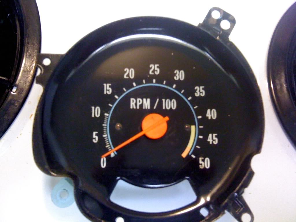
The tachometer system uses a National Semiconductor LM181 with a GM part number on it. if your tach is completely dead you can replace this chip with the NTE01670 as the LM181 is no longer manufactured. this is the other chip that is completely black. not to be confused with the resistor chip. if your tach works at all (responds to engine speed) the LM181 is fine. the resistor chip is the one that looks like this...
the particular resistor that has gone bad is located between pins 4 and 10 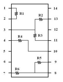
so take out your potentiometer... 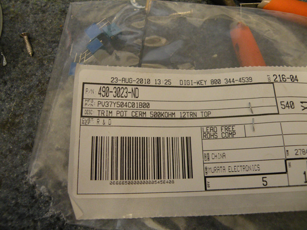
Now after looking at the way that the pins connect to the resistor we have to make sure to cut the correct side. you could accidently disable the capacitor that smooths the motion.. Also remember that we are looking from the Bottom of the chip! 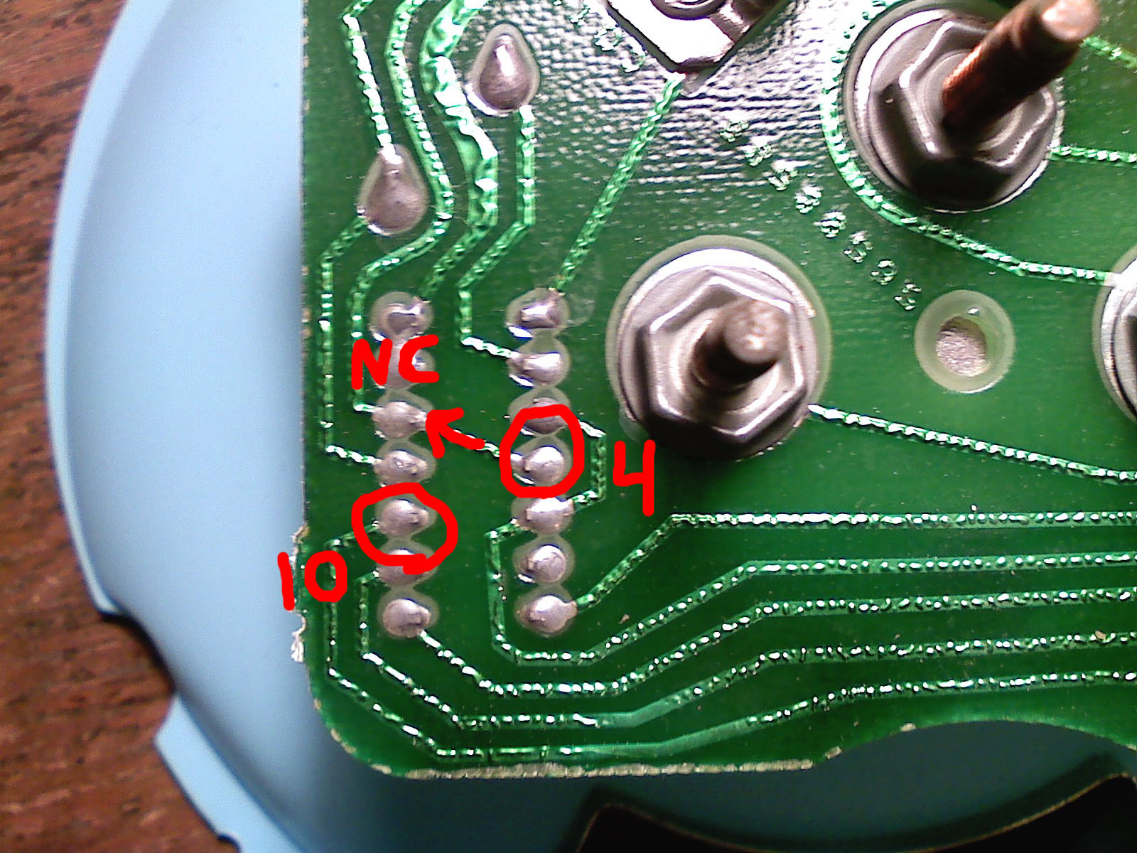
so we see that the one on the left, pin 10, goes away off to the right. so we don't want to cut it for logistics reasons. however pin 4 is set up in such a way that it exits from under the chip by bouncing through pin 12 which is not connected inside the chip. this makes it handy because we can just cut the trace between pin 4 and pin 12. and put our potentiometer between pins 10 and 12. 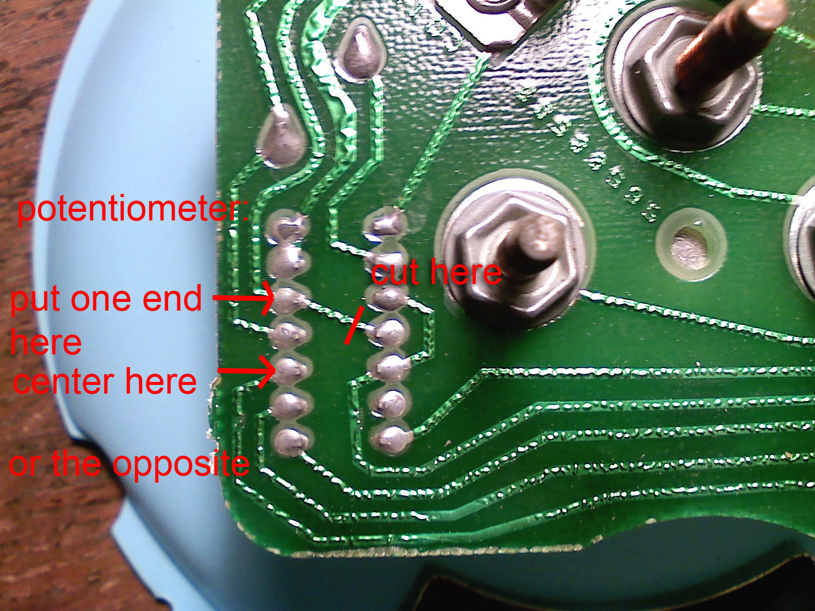
now we have eliminated the original resistor. why did we do that? because if we had just added to it, it will change more and be messed up again. not worth it. just fix it for good. now we'll solder our potentiometer between pin 10 and pin 12. cut off one of the end pins of the potentiometer, we will use one end lead on the pin 10 and the center lead on pin 12. as seen below. 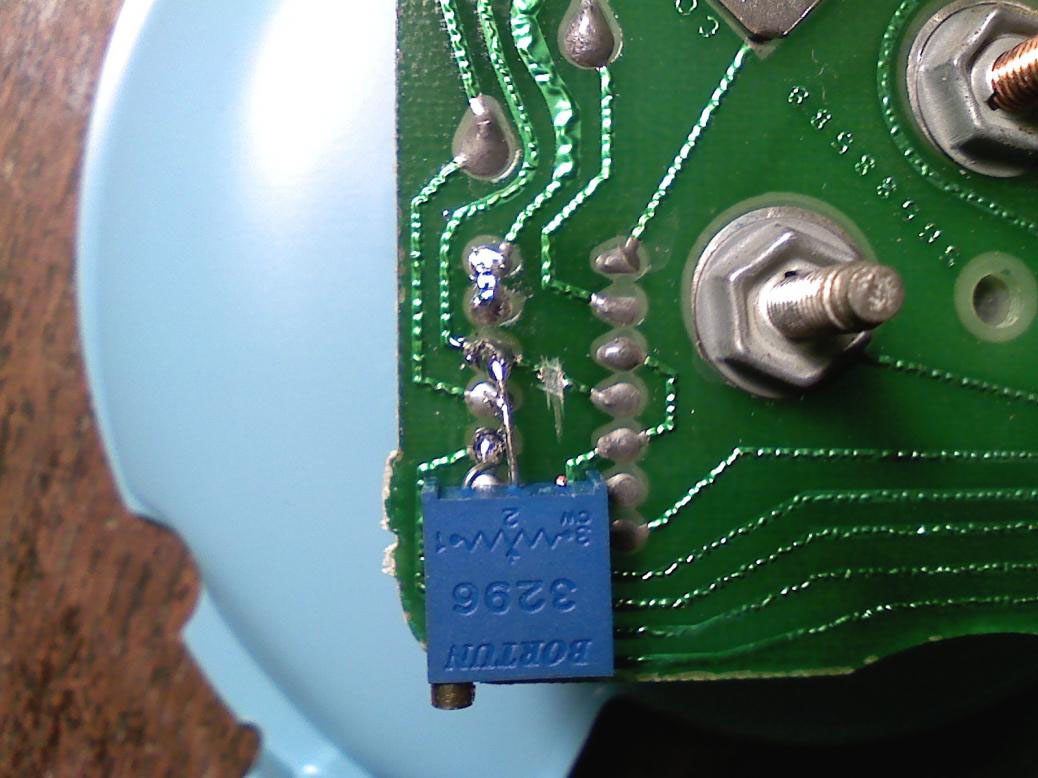
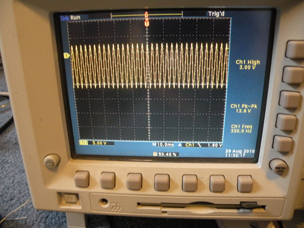
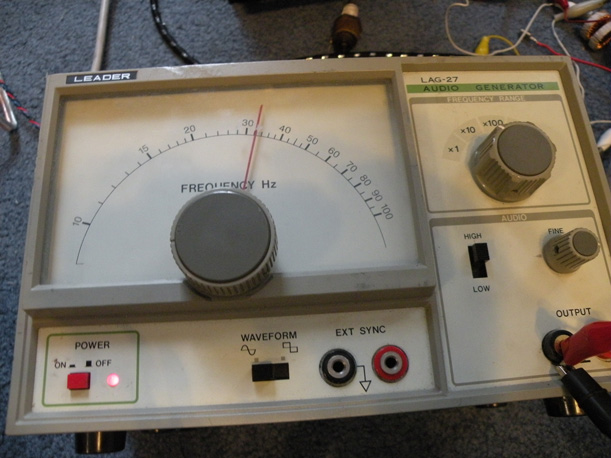
and believe it or not you're done! that's it! well... we still have to calibrate it RPM = { frequency(Hz) x 60(seconds) } / {1/2 # of cylinders} so for a V8 engine it's simply {frequency(Hz) x 15} therefore on a V8 100Hz is 1500 RPM there are multiple ways to do this, fortunately due to my electronics background I have some fancy equipment. either way you will need something that will measure frequency. you can either use a frequency generator or use your engine. if you use your engine you need some other tachometer to calibrate to. and remember to make sure that the tach filter is before the tach or it will blow up. I used a frequency generator and a scope to make sure the frequency was accurate. they were nice enough to label +12v ground and signal on the back of the tach board. so hook up 12 volts to the power pins (bolts). now hook up your frequency generator (or engine tach wire) to the signal pin (bolt). set the frequency of the generator to 100Hz, now adjust the amplitude of the generator until you get a stable RPM measurement on the tach (approx 12-15v). Now just adjust the potentometer until the tach reads 1500 RPM. or with your engine until it matches the working tach. feel free to check the calibration in multiple places, i.e. 300Hz = 4500 RPM and others just to make sure it is mostly linear. 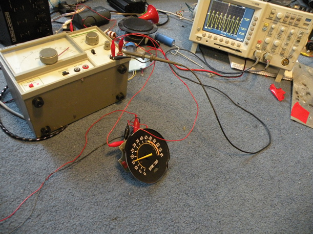
now just put the whole thing back in your car exactly how you took it out and you've got a perfect working tach and bragging rights that you fixed it yourself! |
Home |
|
|
|
| Copyright 2010 AK Motorsports
Sarasota, FL USA |